
0
Owner's of the Samson Music Mixer MIXPAD STEREO MIXERS gave it a score of 0 out of 5. Here's how the scores stacked up:

13
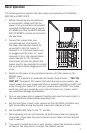
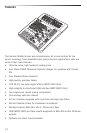
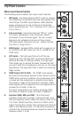
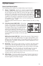
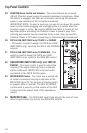
Stereo Input Channel Section
The following section details four stacked stereo input channels.
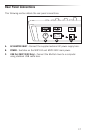
11. Stereo ¼” Input Jacks - Use the ¼” jacks for connecting stereo
line level sources. For stereo inputs use the LINE L to connect
the left channel and the LINE R to connect the right channel.
Use the LEFT input when connecting a mono input signal to
the Stereo Input channels. You can connect outputs from high
impedance microphones, synthesizers and drum machines to
these inputs. The LINE inputs have a nominal operating level
of -40dBV through - 10dBV.
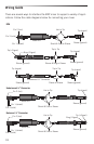
TRS phone jacks Connector pin-out - Sleeve: Ground, Tip: Hot (+), Ring:
Cold (-)
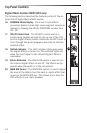
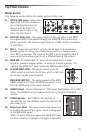
12. FX Auxiliary Control (MXP124FX) - FX Auxiliary
Control - The channel’s FX knob controls the
amount of signal that is sent to the effects bus.
The signal of the FX bus in the MXP124FX is
routed to the Digital Effects section for on-
board signal processing. The FX signal can also
be sent to an external effect device connected
to the FX SEND jack located on the front panel
jack field.
MON Auxiliary Control (MXP124) - Controls the amount of that channel’s
signal that is sent to the MON Output. The signal feeding MON is sent
before, or pre, the channel fader, so the channel fader has no effect on
the MON level. The MON is usually used to create a separate mix for a
floor monitor system.
13. BAL Control - This control is used to place, or position, the stereo signal
into the main left and right stereo mix field. You can create a stereo
image by panning some input signals to the left and others to the right.
14. PEAK Indicator - This LED indicator will flash RED when the channel
input signal peaks. To reduce distortion, turn the LEVEL control
counterclockwise or lower the volume of the input device until the clip
indicator does not light during normal use.
15. LEVEL Control - This knob controls the volume of channel inputs and is
used to continuously adjust the loudness of the various signals being
blended together at the Main Outputs.
Top Panel Controls
11
12
13
14
15
11
12
13
14
15


Find Your Products By Category
Please Login
