
0
Owner's of the Tascam Clock Radio master clock generator gave it a score of 0 out of 5. Here's how the scores stacked up:
10
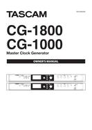
TASCAM CG-1800/CG-1000
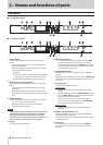
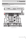
2 – Names and functions of parts
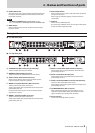
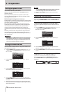
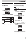
Home Screen
The display of this unit usually shows the following information.
CG-1800
CG-1000
1 Reference clock
This shows the currently selected reference clock.
2 Video clock format (CG-1800 only)
This shows the format setting for the video clock output
from this unit.
3 Video clock frame rate (CG-1800 only)
This shows the frame rate setting for the video clock output
from this unit.
4 Audio clock frequency
This shows the audio clock frequency generated by this unit.
5 Pull-up/pull-down (CG-1800 only)
This shows the pull-up or pull-down setting as a percentage
that is applied to the audio clock frequency generated by
this unit (4).
Information screen
INFO button indicator status
Blue
During ordinary operation, the INFO button indicator lights
blue. When blue, press it to show information about the current
operation status on the display.
Red
When trouble occurs with the unit, the INFO button indicator
lights red. When red, press it to show information about the
error on the display. Press it again to show information about
the current operation status.
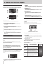
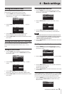
Operation status display (button lit blue)
During ordinary operation (lit blue), press the INFO button to
show information about the current operation status on the
display.
Example of display when reference redundancy function is on
1 WORD IN
This only appears when a 10MHz master clock signal is being
received through the word clock input connector.
2 WORD OUT 11/12
This shows the multiplier setting for the word clock output
from the WORD 11/12 OUTPUTS.
3 AES output format
This shows the format setting for the digital audio clock
signal output from the AES3/11 1/2 OUTPUTS (balanced
XLR).
4 S/PDIF output format
This shows the format setting for the digital audio clock
signal output from the S/PDIF 1/2 OUTPUTS (RCA pin jacks).
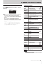
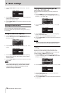
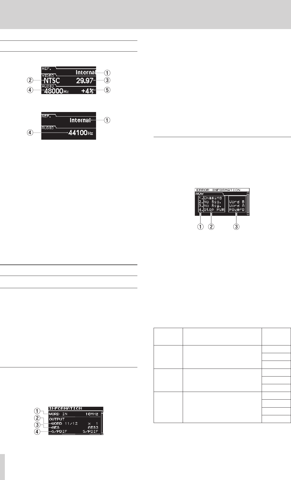
Error information screen (button lit red)
When trouble occurs with the unit, the INFO button lights red.
Press it to show the following information about the trouble on
the display.
8
Display of errors occurring currently
Trouble that is occurring currently is shown one item per line.
Example of current error display
1 Order number
Numbers assigned to errors in the order of occurrence.
2 Error details
This shows the error code and signal affected as described
in the Overview of error codes table blow. (See “Overview of
error codes” on page 10.)
3 Signal with error
This shows the signal with which the error occurred.
8
Overview of error codes
The error codes that appear on the
ERROR INFORMATION
screen are as follows.
Error code
shown
Error code explanation
Signal
affected by
error
Unlock
The operation reference signal
became unlocked, and the unit
switched to the secondary reference
clock or backup reference clock.
WORD
VIDEO
AES
No Signal
There is no operation reference
signal being input, so the unit
switched to the secondary reference
clock or backup reference clock.
WORD
VIDEO
AES
Chasing
Switching reference clock. (This is
not listed in the display of errors
occurring currently.)
WORD
VIDEO
AES
INTERNAL


Find Your Products By Category
Please Login
