
0
Owner's of the Yamaha Musical Instrument MG16 16 Channel Mixer gave it a score of 0 out of 5. Here's how the scores stacked up:
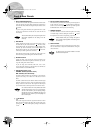
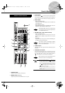
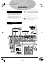
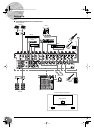
Front & Rear Panels
MG16/6FX
22
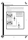
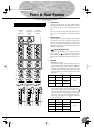
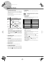
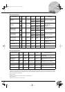
8 Level-Meter Signal Switches
These level-meter switches, together with the channel PFL
switches, select the signal that is sent through the
C-R/PHONES control to the C-R OUT jacks, the PHONES
jack, and the level meter.
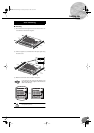
The following illustration shows how the switch settings corre-
spond to the signal selection.
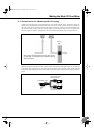
1
If the input channel’s PFL switch is on ( ), then only the
channel’s PFL output it sent to the C-R OUT jacks, PHONES
jacks, and level meter.
2
If the 2TR IN switch is on ( ), the signal supplied to the 2TR
IN jack is sent to the C-R OUT jacks, PHONE jacks, and level
meter. If the 2TR IN switch is off ( ), then either the Stereo,
Group 1-2, or Group 3-4 signal is sent to the C-R OUT jacks
(as determined by the ST-GROUP and GROUP toggle
switches).
9 C-R/PHONES Control
Controls the level of the signal output to the PHONES jack and
the C-R L and R jacks.
0 Level Meter
This LED display shows the level of the signal selected by the
selection switches described in
8 above (the level to the C-R
OUT and PHONES jacks). The “0” point corresponds to the
standard output level. The indicator lights up red when the out-
put hits the clipping level.
A POWER Indicator
This indicator lights up when the mixer’s power is ON.
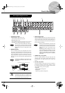
B ST GRAPHIC EQUALIZER
This 7-band equalizer adjusts the sound of the signal send to
the ST OUT jacks. The equalizer is effective only if the GEQ
switch is set on ( ). The equalizer cuts or boosts each band
(125, 250, 500, 1k, 2k, 4k, and 8k Hz) over a range of ±12 dB.
C PHONES Jack
Connector for headphones. This is a balanced stereo phone-type
output jack.
The signal monitored by these jacks is selected by
the Level-Meter Signal switches and the channel
PFL switches.
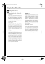
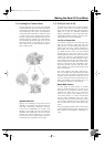
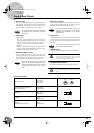
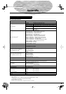
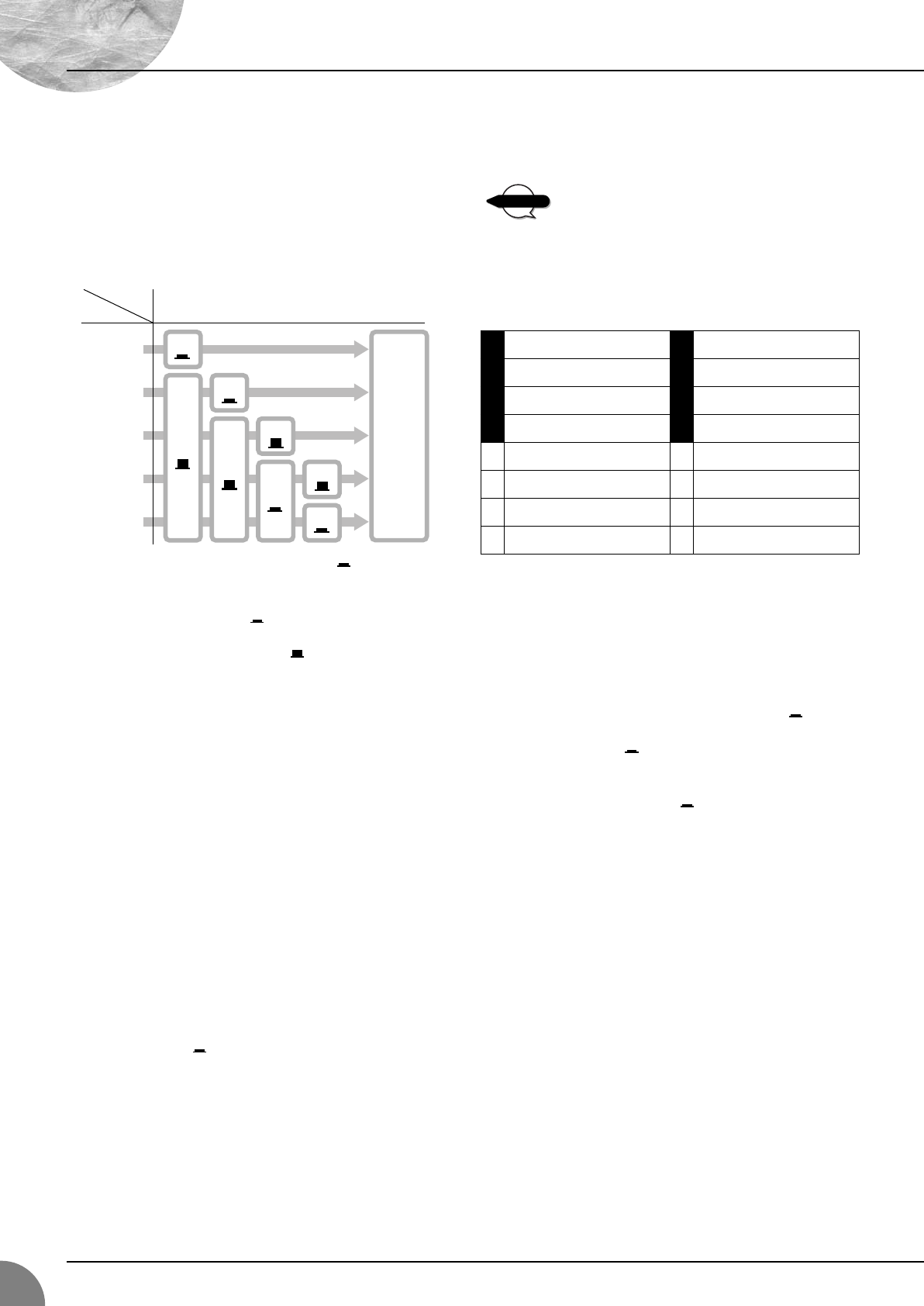
D DIGITAL EFFECT
• PROGRAM Dial
Selects the internal digital effect to be applied. You can select
from 16 effects, as shown in the table.
• PARAMETER Control
Adjusts the parameter (depth, speed, etc.) for the selected
effect.
• AUX1 and AUX2 Controls
Adjust the level of the signal sent from the internal digital
effector to the AUX1 and AUX2 buses.
• ON Switch
Switches use of the internal effect on or off. The internal
effect is applied only if this switch is turned on ( ).
• PFL Switch
Set this switch on ( ) if you wish to output the effect signal
to the PFL bus.
• GROUP Switches (1-2, 3-4)
Set one or both switches on ( ) to output the internal effect
signal to the GROUP 1-2 and/or GROUP 3-4 buses.
• EFFECT RTN Fader
Adjusts the signal level from the internal digital effector to
the STEREO bus.
2TR - IN
2TR IN
PFL
PFL
ST
GROUP 3 - 4
ST-GROUP GROUP
GROUP 1 - 2
ON
OFF
ON
ON
ON
OFF
OFF
OFF
C-R OUT
&
PHONES
Switch
Signal
12
1 HALL 1 9 VOCAL ECHO 1
2 HALL 2 10 VOCAL ECHO 2
3 HALL 3 11 VOCAL ECHO 3
4 ROOM 12 VOCAL ECHO 4
5 PLATE 1 13 VOCAL REVERB 1
6 PLATE 2 14 VOCAL REVERB 2
7 PLATE 3 15 VOCAL REVERB 3
8 GATE REVERB 16 VOCAL REVERB 4
NOTE
MG16-6FX.book Page 22 Saturday, January 25, 2003 10:13 AM


Find Your Products By Category
Please Login
