
0
Owner's of the Yamaha Musical Instrument MG16 16 Channel Mixer gave it a score of 0 out of 5. Here's how the scores stacked up:
Precautions
MG16/6FX
3
—For correct operation —
●
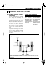
XLR-type connectors are wired as follows
Pin 1: ground; Pin 2: hot (+); Pin 3: cold (–).
●
INSERT TRS phone jacks are wired as follows
Sleeve: ground; Tip: send; Ring: return.
●
The performance of components with movable contacts—such
as switches, rotary controls, faders, and connectors—deteriorates
over time. While the rate of wear may vary greatly according to
usage conditions, some amount of wear is unavoidable. When
parts wear out, consult your dealer about appropriate replace-
ments.
●
Use of a mobile phone near this unit may induce noise. If noise
occurs, move the phone further from the unit.
Copying of commercially available music data and/or digital audio files, except for personal use, is strictly prohibited.
Illustrations in this manual are for explanatory purposes only, and may not match the actual appearance of the product during operation.
Company names and product names used in this Owner’s Manual are trademarks or registered trademarks of their respective owners.
* This applies only to products distributed by YAMAHA CORPORATION OF AMERICA. (class B)
• This applies only to products distributed by Yamaha-Kemble Music (U.K.) Ltd. (2 wires).
Connector pin assignments
Replacement of Consumable Parts
Interference from Cell Phones
●
Always turn the power off when the mixer is not in use.
●
Even when the power switch is in the “STANDBY” position, electricity is still flowing to the mixer at the minimum level. When you are
not using the mixer for a long time, make sure you unplug the AC power adaptor from the wall AC outlet.
IMPORTANT NOTICE FOR THE UNITED KINGDOM
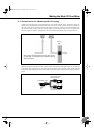
Connecting the Plug and Cord
IMPORTANT. The wires in this mains lead are coloured in accordance with the following code:
BLUE : NEUTRAL
BROWN : LIVE
As the colours of the wires in the mains lead of this apparatus may not correspond with the coloured makings identifying the terminals in your
plug proceed as follows:
The wire which is coloured BLUE must be connected to the terminal which is marked with the letter N or coloured BLACK.
The wire which is coloured BROWN must be connected to the terminal which is marked with the letter L or coloured RED.
Making sure that neither core is connected to the earth terminal of the three pin plug.
1. IMPORTANT NOTICE: DO NOT MODIFY THIS UNIT!
This product, when installed as indicated in the instructions con-
tained in this manual, meets FCC requirements. Modifications
not expressly approved by Yamaha may void your authority,
granted by the FCC, to use the product.
2. IMPORTANT: When connecting this product to accessories
and/or another product use only high quality shielded cables.
Cable/s supplied with this product MUST be used. Follow all
installation instructions. Failure to follow instructions could void
your FCC authorization to use this product in the USA.
3. NOTE: This product has been tested and found to comply with
the requirements listed in FCC Regulations, Part 15 for Class “B”
digital devices. Compliance with these requirements provides a
reasonable level of assurance that your use of this product in a
residential environment will not result in harmful interference with
other electronic devices. This equipment generates/uses radio
frequencies and, if not installed and used according to the
instructions found in the users manual, may cause interference
harmful to the operation of other electronic devices. Compliance
with FCC regulations does not guarantee that interference will
not occur in all installations. If this product is found to be the
source of interference, which can be determined by turning the
unit “OFF” and “ON”, please try to eliminate the problem by using
one of the following measures:
Relocate either this product or the device that is being affected by
the interference.
Utilize power outlets that are on different branch (circuit breaker
or fuse) circuits or install AC line filter/s.
In the case of radio or TV interference, relocate/reorient the
antenna. If the antenna lead-in is 300 ohm ribbon lead, change
the lead-in to co-axial type cable.
If these corrective measures do not produce satisfactory results,
please contact the local retailer authorized to distribute this type
of product. If you can not locate the appropriate retailer, please
contact Yamaha Corporation of America, Electronic Service Divi-
sion, 6600 Orangethorpe Ave, Buena Park, CA90620
The above statements apply ONLY to those products distributed
by Yamaha Corporation of America or its subsidiaries.
FCC INFORMATION (U.S.A.)
MG16-6FX.book Page 3 Saturday, January 25, 2003 10:13 AM


Find Your Products By Category
Please Login
