
0
Owner's of the Tascam Welding System master clock generator gave it a score of 0 out of 5. Here's how the scores stacked up:
10
TASCAM CG-2000
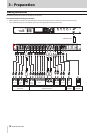
2 – Names and functions of parts
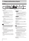
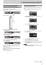
Home Screen
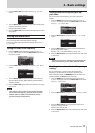
The display of this unit usually shows the following information.
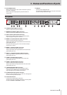
1 Reference clock
This shows the currently selected reference clock.
2 Video clock format
This shows the format setting for the video clock output
from this unit.
3 Video clock frame rate
This shows the frame rate setting for the video clock output
from this unit.
4 Audio clock frequency
This shows the audio clock frequency generated by this unit.
5 Pull-up/pull-down
This shows the pull-up or pull-down setting as a percentage
that is applied to the audio clock frequency generated by
this unit (4).
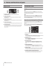
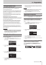
Information screen
INFO button indicator status
Blue
During ordinary operation, the INFO button indicator lights
blue. When blue, press it to show information about the current
operation status on the display.
Red
When trouble occurs with the unit, the INFO button indicator
lights red. When red, press it to show information about the
error on the display. Press it again to show information about
the current operation status.
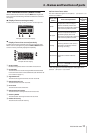
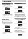
Operation status display (button lit blue)
During ordinary operation (lit blue), press the INFO button to
show information about the current operation status on the
display.
When the reference redundancy function is on, the
INFOR-
MATION
screen will have 2 pages. Turn the MULTI JOG dial to
scroll through the pages.
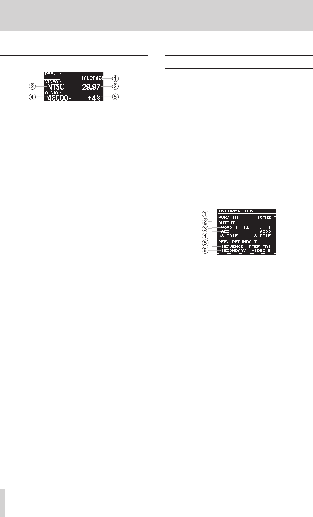
Example of display when reference redundancy function is on
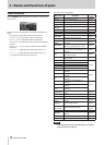
1 WORD IN
This only appears when a 10MHz master clock signal is being
received through the word clock input connector.
2 WORD OUT 11/12
This shows the multiplier setting for the word clock output
from the WORD 11/12 OUTPUTS.
3 AES output format
This shows the format setting for the digital audio clock
signal output from the AES3/11 1/2 OUTPUTS (balanced
XLR).
4 S/PDIF output format
This shows the format setting for the digital audio clock
signal output from the S/PDIF 1/2 OUTPUTS (RCA pin jacks).
5 Sequence mode
When the reference redundancy function is on, this shows
the mode used to switch the reference redundancy clock.
6 Secondary reference clock selection status
When the reference redundancy function is on, this shows
the selection status of the secondary reference clock.


Find Your Products By Category
Please Login
