

0
Owner's of the Tascam Welding System master clock generator gave it a score of 0 out of 5. Here's how the scores stacked up:
TASCAM CG-2000
9
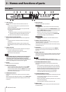
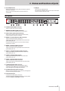
2 – Names and functions of parts
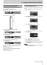
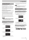
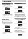
r EXIT/CANCEL button
When a setting screen is open, press this button to go back
one level in the menu.
When a pop-up message appears, press this button to
answer “NO”.
t USB port
Use to connect USB flash drives.
By connecting a USB flash drive, you can export and import
presets and output operation logs.
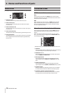
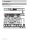
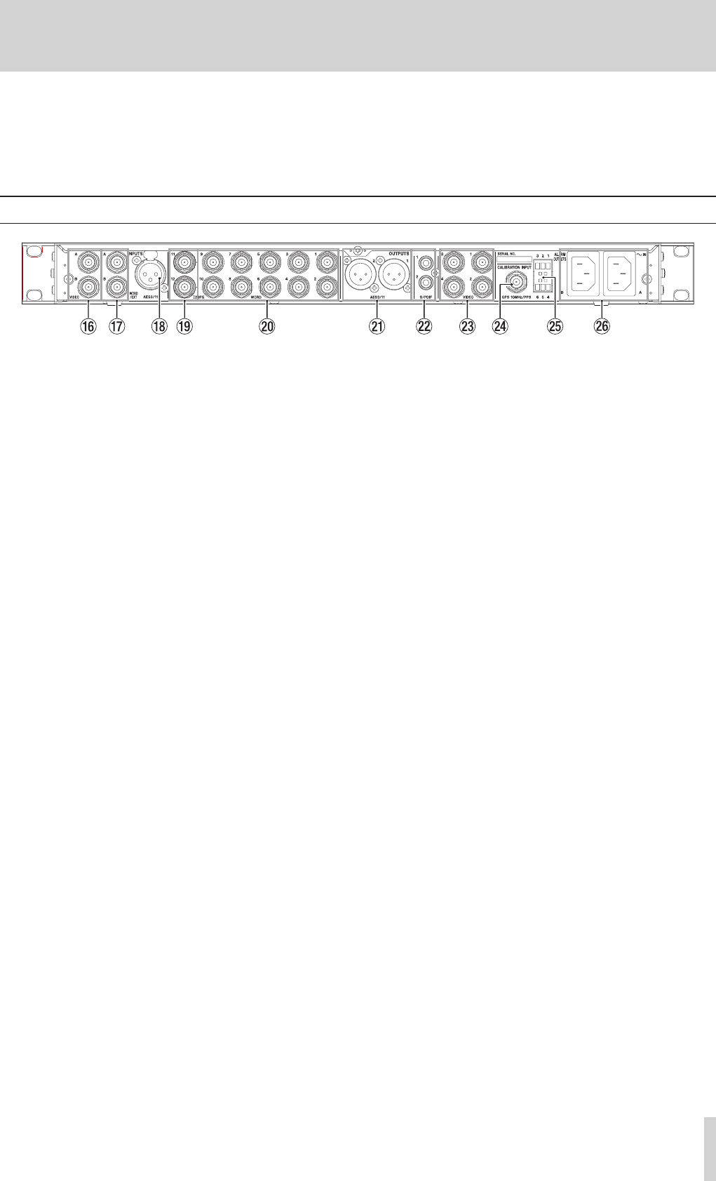
Rear panel
y VIDEO A/B INPUTS (BNC connectors)
These are video clock input connectors.
u WORD/EXT A/B INPUTS (BNC connectors)
These are word clock/10MHz clock input connectors
i AES3/11 INPUT (balanced XLR connector)
When using an AES3 or AES11 signal as reference clock,
input the signal through this connector.
o WORD 11/12 (256Fs) OUTPUTS (BNC connectors)
These are word clock output connectors.
These output word clock signals based on the audio clock
generated by this unit.
Using the menu setting, you can also set these to output
signals with a ×256 Fs.
p WORD 1–10 OUTPUTS (BNC connectors)
These are word clock output connectors.
These output word clock signals based on the audio clock
generated by this unit.
a AES3/11 1/2 OUTPUTS (balanced XLR connectors)
These output AES3/11 signals based on the audio clock
generated by this unit.
s S/PDIF 1/2 OUTPUTS (RCA pin jacks)
These output S/PDIF signals based on the audio clock
generated by this unit.
d VIDEO 1–4 OUTPUTS (BNC connectors)
These are video clock output connectors.
These output video clock signals based on the video clock
generated by this unit.
f CALIBRATION INPUT (BNC connector)
When calibrating this unit’s internal oscillator, input a
calibration signal (10MHz signal generated from a GPS
signal, PPS signal, etc.) through this connector.
g ALARM OUTPUTS (Euroblock connector)
When an error, for example, occurs in this unit, messages can
be sent out through this connector.
h AC IN A/B connectors
Connect the included power cords here.
To operate this unit with power redundancy, connect power
to both the AC IN A and AC IN B connectors.


Find Your Products By Category
Please Login
