
0
Owner's of the Tascam Welding System master clock generator gave it a score of 0 out of 5. Here's how the scores stacked up:

26
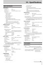
TASCAM CG-2000
9 – Other functions
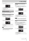
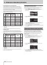
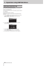
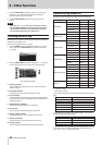
Alarm output
This unit has a function that allows it to output an alarm through
a dedicated connector when trouble occurs. To use this function,
just connect the
ALARM OUTPUTS
connectors as required.
ALARM OUTPUTS connectors
Pin Details
1 +5V
2 Outputs when there is an unchecked error log
3 GND
4 +5V
5 Outputs while an error is occurring.
6 GND
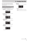
Power redundancy function
This unit has two power supply circuits, and supports redun-
dancy to prevent problems related to the power supply.
By default, the power redundancy function is off. If you want
to use it, follow the procedures below to turn this function on
and connect two different power supplies to the two power
connectors.
If the power redundancy function is on when only one of
the power circuits is connected, the unit will determine that
one power supply has been interrupted and the POWER
REDUNDANT indicator on its front will blink. In this case, turn
the power redundancy function off.
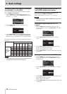
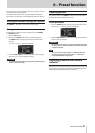
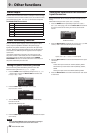
Setting the power redundancy function
You can turn the power redundancy function on or off.
Make this setting from the
UTILITY 1
page.
1. Press the MENU button repeatedly to open the
UTILITY
1
menu page, and turn the MULTI JOG dial to select the
POWER RED.
item.
2. Press the MULTI JOG dial to open the
POWER
REDUNDANT
screen.
3. Turn the MULTI JOG dial to turn the power redundancy
function on or off.
Options: OFF (default), ON
4. Press the MULTI JOG dial to confirm the selection and return
to the menu.
NOTE
Press the EXIT/CANCEL button while making a setting to
cancel the change and return to the menu screen.
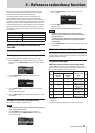
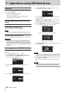
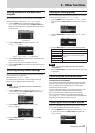
Setting the termination for reference
input connectors
Set the termination for each input connector according to the
wiring.
Make these settings on the
TERMINATION
page.
1. Press the MENU button repeatedly to open the
TERMI-
NATION
menu page, and turn the MULTI JOG dial to select
the input connector for which you want to set the termi-
nation.
VIDEO A selected
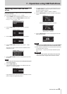
2. Press the MULTI JOG dial to open the
TERMINATION
XXX
screen (“ XXX” is the name of the input connector).
TERMINATION VIDEO A
screen open
3. Turn the MULTI JOG dial to set the termination for the input
connector.
Options
Video clock input connector: 75ohm (default), OPEN
Word clock input connector: 75ohm (default), 50ohm,
OPEN
GPS signal input connector: 50ohm (default), OPEN
4. Press the MULTI JOG dial to confirm the selection and return
to the menu.


Find Your Products By Category
Please Login
