
0
Owner's of the Pioneer DJ Equipment Pioneer DJ Equipment gave it a score of 0 out of 5. Here's how the scores stacked up:
En
8
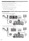
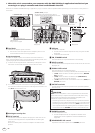
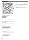
When this unit is connected to your computer with the RMX-500 Plug-in application installed and you
are using it as a plug-in controller and sound card/USB audio interface
When this unit detects the RMX-500 Plug-in application, plug-in controller mode is operated. Effects processing is not carried out on this product in
such cases.
R
L
R
L
2
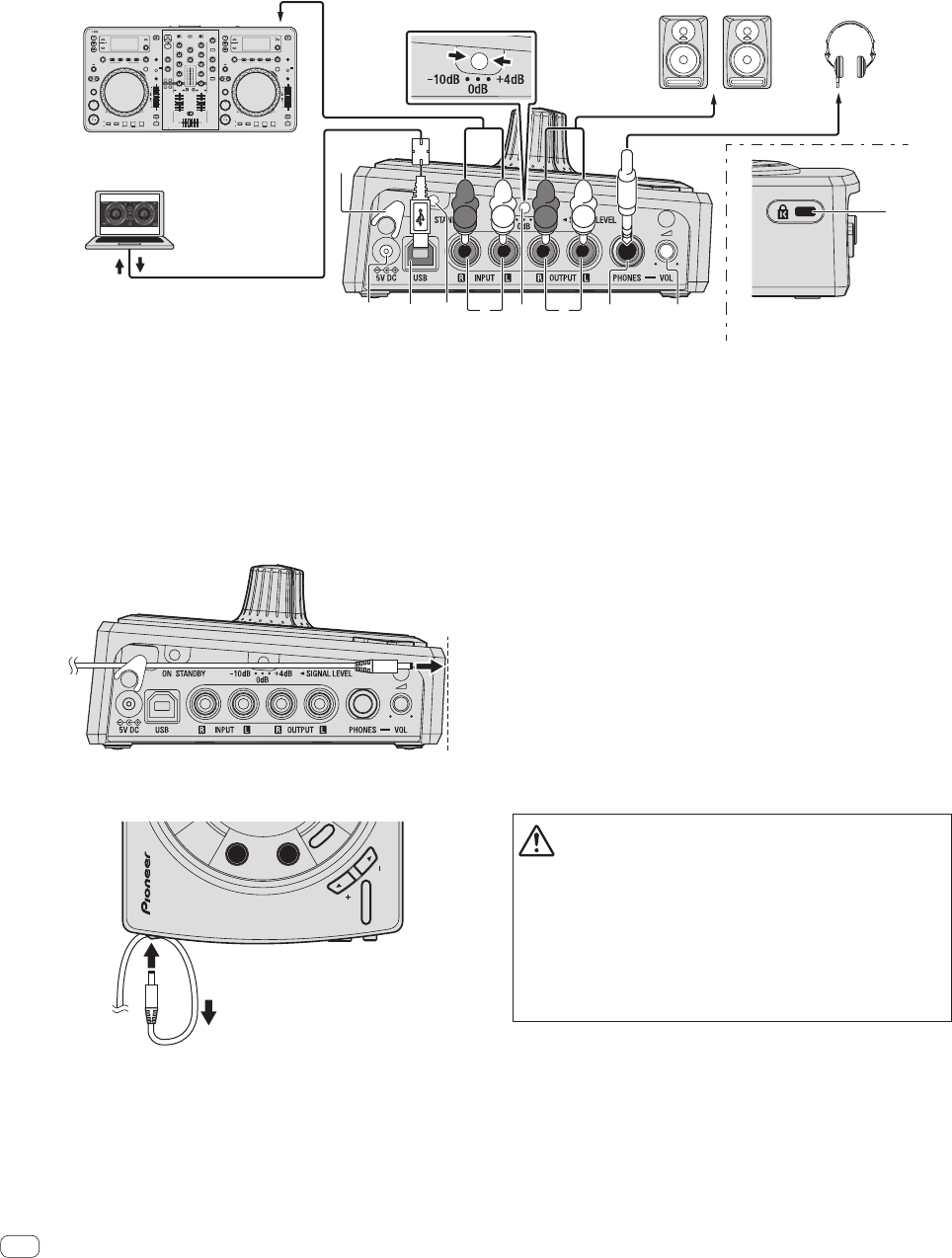
Headphones
USB audio out
USB audio in
/
Plug-in control signal
Rear panelSide panel
To audio input
terminals
To [
MASTER OUT
] terminal
Computer
Powered speakers, etc.
DJ system
0
10
9
8
7
6
5
4
3
2
1
0
10
9
8
7
6
5
4
3
2
1
0
ABC
0
3
4
5 7 a986
1
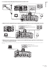
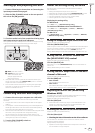
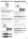
[
SIGNAL LEVEL
] switch
Set the switch so that the signal level is
suitable for the devices connected to this unit.
1 Cord hook
Hook the AC adapters’ power cord here.
! The sound will be interrupted if the AC adapter’s power cord is
disconnected from the unit during playback.
Using the cord hook
Hook the AC adapter’s power cord onto the cord hook to fasten it in
place. This prevents the power cord from being accidentally pulled, caus-
ing the plug to get disconnected from the terminal.
1 As shown on the diagram below, extend the tip of the power cord to
side of this unit and hook the power cord onto the cord hook.
2 Turn the tip of the power cord so that it is facing towards you, then
turn it back to create a ring as shown in the diagram and insert it into
the [5V DC] terminal of this unit.
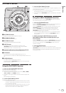
OVER
DUB
EXIT
4-BEAT
SEQUENCER
LEVEL
K
I
C
K
R
O
L
L
INSTRUMENT
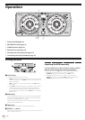
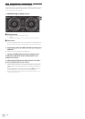
2 Kensington security slot
3 5V DC terminal
Connect the included AC adapter’s DC plug here. Wait until all con-
nections of the equipment are completed before connecting the
power cord.
Be sure to use the power cord and AC adapter included with this
product.
4 USB port
Connect to a computer.
! Connect this unit and the computer directly using the included
USB cable.
! A USB hub cannot be used.
5 ON, STANDBY switch
This switches this unit’s power between on and standby.
6 INPUT terminals
Connect to the external output terminals of a DJ mixer, DJ controller,
DJ player, etc.
7 SIGNAL LEVEL switch
This switches this unit’s input/output gain.
Set as shown below, according to the devices connected to this unit.
— [+4 dB]: Select this when connecting to a DJ mixer’s [MASTER
OUT] terminals.
—
[+0 dB]: Select this when connected to the [MASTER OUT]
terminals of a DJ mixer or DJ controller.
—
[–10 dB]: Select this when connected to a DJ mixer’s [SEND] and
[RETURN] terminals.
8 OUTPUT terminals
Connect these to the external input terminals of powered speakers,
a DJ mixer, etc.
CAUTION
Interconnect the equipment in such a way that the flow of the audio
signals does not loop. If looped connections are made, the circuitry
could produce oscillations that may damage the speakers, etc.
Examples of looped connections to be avoided
! Connecting a DJ mixer’s output to this unit’s input terminals then
inputting this unit’s output to the same DJ mixer’s input terminals.
! Connecting the output from a DJ mixer’s [SEND] terminals to this
unit’s input terminals then inputting this unit’s output to input ter-
minals other than the [RETURN] terminals on the same DJ mixer.
9 PHONES terminals
Connect headphones here.
! Connect headphones with an impedance of 32 W or more.
Headphones with an impedance of less than 32 W are not
supported.
a HEADPHONES VOL control
Adjusts the audio level output from the [PHONES] terminal.


Find Your Products By Category
Please Login
