
0
Owner's of the Shure Microphone Wireless System gave it a score of 0 out of 5. Here's how the scores stacked up:
6
Quick Start
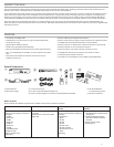
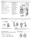
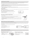
Step 1: Power and Antenna Connection
① Connect an antenna to each of the antenna connectors.
② Connect the power supply to the receiver and plug into an AC power
source.
③ Connect the receiver audio output to a mixer or amplifier.
④ Press and hold the power button to turn on the receiver.
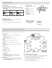
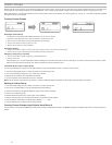
Step 2: Scanning for the Best Available Channel
1. Press the
menu button on the receiver to access the scan function.
menu
enter
audio rf
ir
sync
I
I
I
I
I
I
I
I
I
I
I
I
I
I
I
I
I
I
I
I
I
I
I
I
I
I
I
I
I
I
I
I
I
I
I
I
I
I
I
I
I
I
I
I
I
I
I
group channel
scan
2. Press the enter button to start a frequency scan. The scan icon will flash while
in scan mode. When the scan is complete, the selected group and channel
appear on the display.
menu
enter
audio rf
ir
sync
group channel rf audio gain
dB
TV
MHz
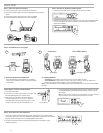
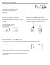
Step 3: Install Batteries into Transmitter
AA Batteries Shure SB900 Battery
on
n
o
2D
X
LU
on
AA Adapter AA Adapter
① Accessing the Battery Compartment
Press the side tabs on the bodypack or unscrew the
cover on the handheld as shown to access the battery
compartment.
② Installing Batteries
- AA Batteries: Place batteries (note polarity markings) and AA Adaptor as shown
- Shure SB900 Battery: Place battery as shown (note polarity markings), remove AA Adaptor from
bodypack transmitter, stow AA Adaptor in door for handheld transmitter
Note: If using AA batteries, select a battery type from the transmitter menu to ensure accurate battery
metering.
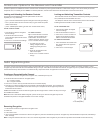
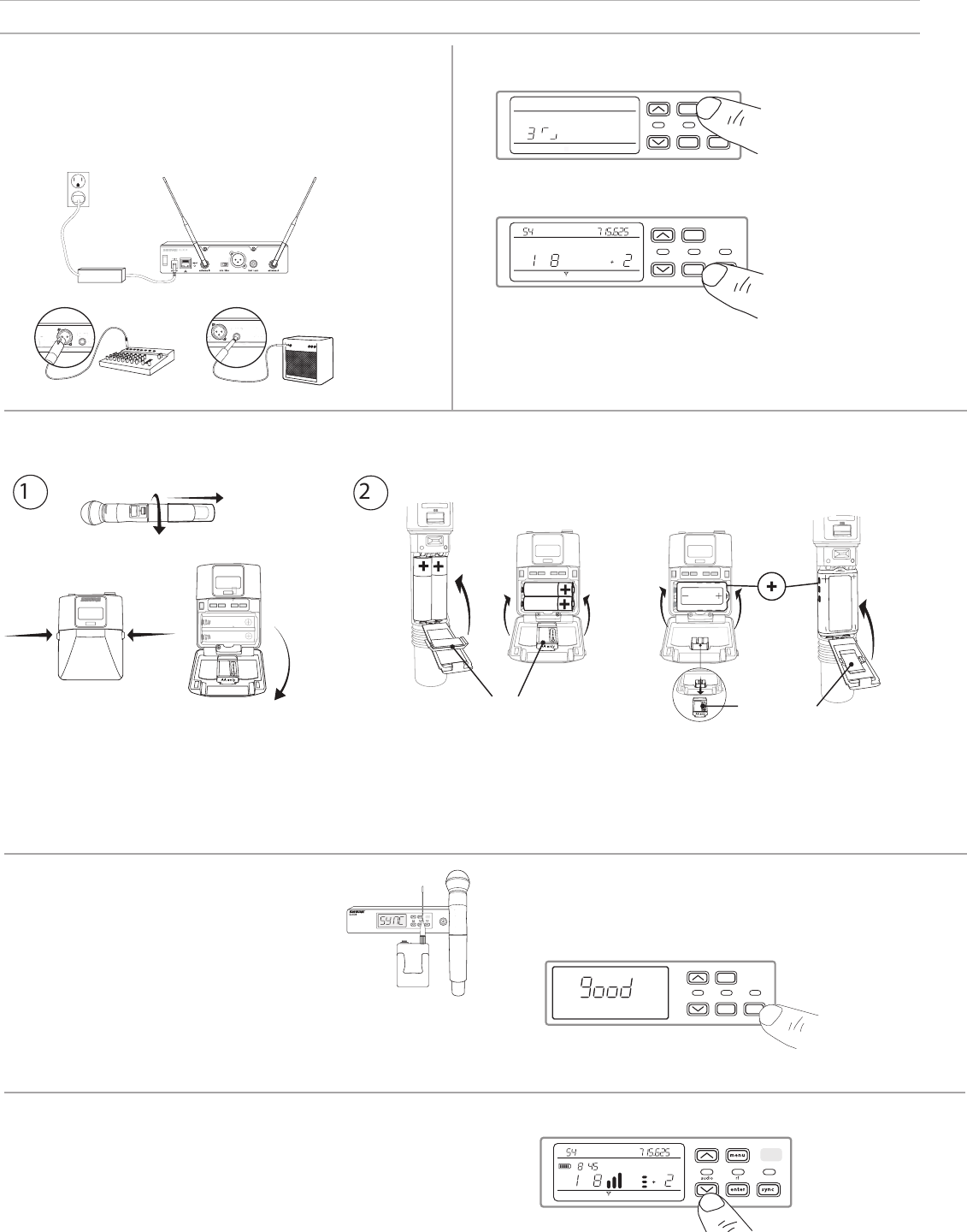
Step 4: IR Sync to Create an Audio Channel
1. Turn on the transmitter.
2. Press the
sync button on the receiver. The red ir LED
will blink indicating that sync mode is active.
3. Align the IR sync windows of the transmitter and
receiver at a distance of <15 cm (6 in.). When the
transmitter and receiver are aligned, the red ir LED
remains on and the sync will automatically occur.
< 15 cm (6 in.)
4. sync good appears on the display when IR sync is complete. The blue
rf LED will illuminate indicating that the transmitter is within range of
the receiver.
Note: If the IR sync fails, repeat the IR sync procedure, carefully maintaining
alignment between the IR windows of the transmitter and receiver.
menu
enter
audio rf
ir
sync
l
l
l
l
l
l
l
l
l
l
l
l
l
l
l
l
l
l
l
l
l
l
l
l
l
l
l
l
l
l
l
l
l
l
l
l
l
l
l
l
l
l
l
l
l
l
l
l
l
l
l
l
l
l
l
l
l
l
l
l
l
l
l
l
l
l
l
l
l
l
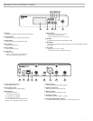
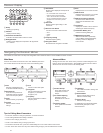
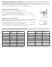
Step 5: Sound Check and Gain Adjustment
1. Test the transmitter at performance levels while monitoring the audio meter and the
audio LED. The audio meter should display at least 3 bars and the audio LED should
be green. Reduce the gain if there is audible distortion of the audio.
2. Increase or decrease the gain if necessary by pressing the arrow buttons on the
receiver front panel.
group channel rf audio gain
dB
TV
MHz
hr mn
INSTRUMENT OUT
INSTRUMENT OUT
PS23


Find Your Products By Category
Please Login
