
0
Owner's of the Yamaha Music Mixer Yamaha Music Mixer gave it a score of 0 out of 5. Here's how the scores stacked up:
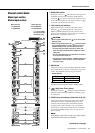
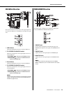
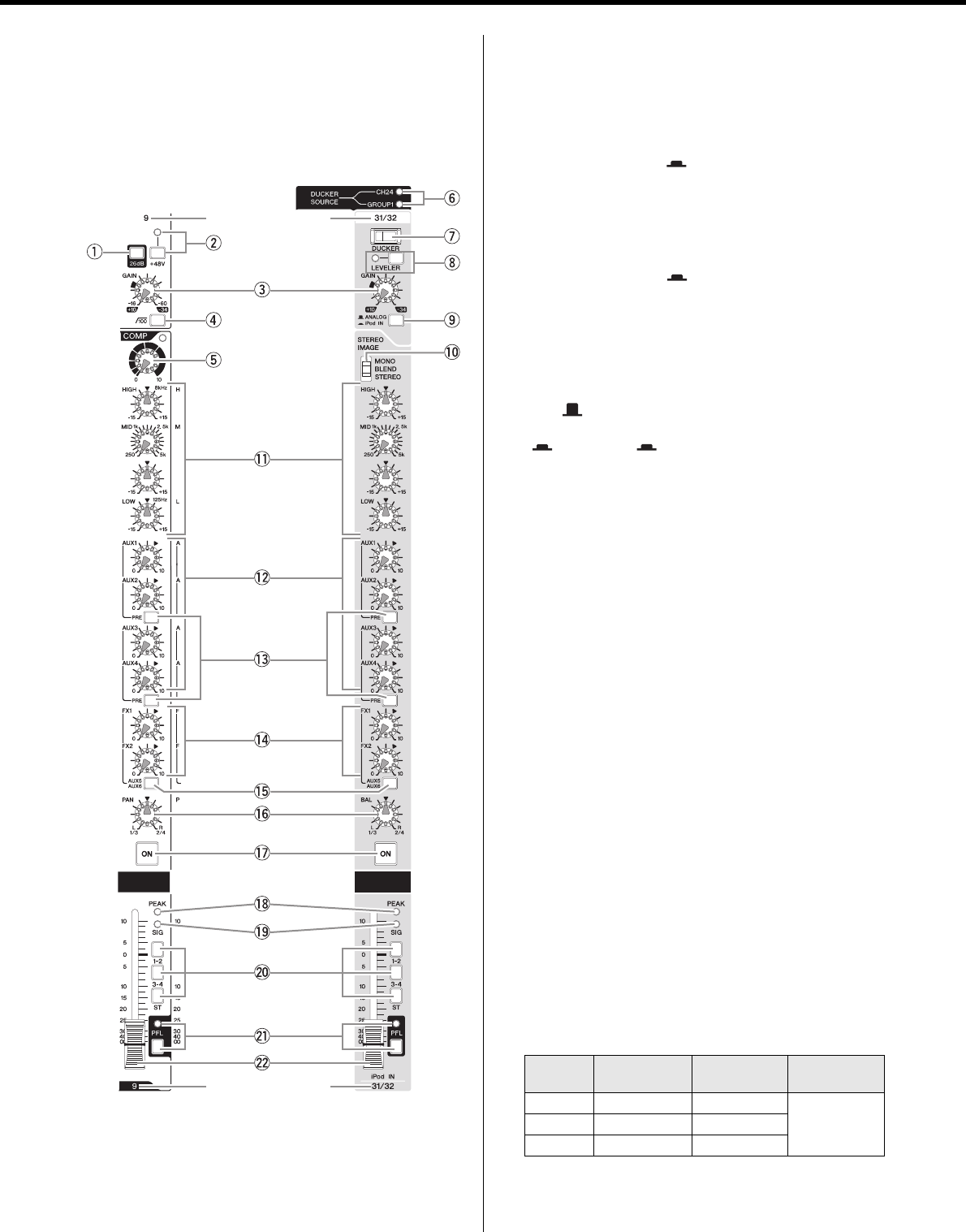
Controls and Connectors
MGP32X/MGP24X Owner’s Manual
12
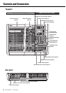
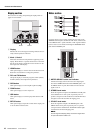
y DUCKER SOURCE indicator
The indicator of the selected input source (CH24 {CH16} or
GROUP1) comes on. The input source can be selected on the
display (page 37).
u DUCKER switch
Turning this switch on ( ) lowers the volume of the stereo
channel automatically when a signal exceeding a certain level
is input to the input source (CH24 {CH16} or GROUP1).
When the switch is turned on, the switch’s lamp comes on.
i LEVELER switch and indicator
Turning this switch on ( ) allows the volume to be
adjusted automatically to a certain level, when the actual
sound output level differs for each song. The indicator is on
when the switch is on.
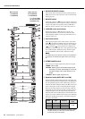
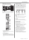
o Input select switch
Selects the input signal source. If this switch is set to ANA-
LOG( ), the jacks for CH29/30 and 31/32 {CH21/22, 23/
24} will be the input source. If this switch is set to USB IN
( ) or iPod IN ( ), the signal from an USB device or
iPod/iPhone will be the input source. The signal from an USB
device will be input to CH29/30 {21/22}, while the signal
from an iPod/iPhone will be input to CH31/32 {23/24}.
NOTE
The GAIN knobs do not affect the volume of your iPod/iPhone.
To adjust the pre-channel-fader signal volume, refer to page
36.
!0 STEREO IMAGE switch
Selects the type of output signal for the input stereo signal.
• MONO : Mono signal
• BLEND : Stereo signal in which left and right inputs
are mixed at a certain percentage for a more nat-
ural stereo image, and in which the pan is con-
trolled.
• STEREO : Stereo signal (original, as is)
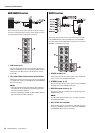
!1 Equalizer knobs (HIGH, MID, and LOW)
This three-band equalizer changes the tone of the high, mid,
and low frequency bands. Turning the knob to the right boosts
the corresponding frequency band, while turning to the left
attenuates the band. Setting the knob to the “t” position pro-
duces a flat response in the corresponding band. The upper
knob sets the center frequency for the mid range, while the
lower knob sets the amount of attenuation or boost (counter-
clockwise/clockwise) for the range. For the CH25/26 and
CH27/28 {CH17/18 and CH19/20}, the attenuation/boost can
only be set at a fixed 2.5kHz center frequency. The following
table shows the EQ type, frequency, and cut/boost range for
each of the three bands.
* The MID frequency can be adjusted from 250Hz to 5kHz.
The MID frequency is 2.5kHz when the MID frequency
control is set at the center position.
Mono channels
1–24 (MGP32X)
1–16 (MGP24X)
Stereo channels
25–32 (MGP32X)
17–24 (MGP24X)
* y-!0 are for CH29/
30, CH31/32 {CH21/
22,CH23/24} only.
Channel number
Channel number
Band Type Frequency
Cut/Boost
range
HIGH Shelving 8kHz
±15dBMID Peaking 2.5kHz*
LOW Shelving 125Hz


Find Your Products By Category
Please Login
