
0
Owner's of the Yamaha Music Mixer Yamaha Music Mixer gave it a score of 0 out of 5. Here's how the scores stacked up:
MGP32X/MGP24X Owner’s Manual
45
Appendix
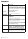
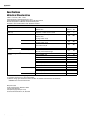
FX2 SPX (14: SYMPHONIC)
FX2 SPX (15: DOUBLER)
FX2 SPX (16: RADIO VOICE)
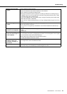
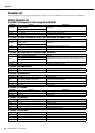
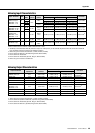
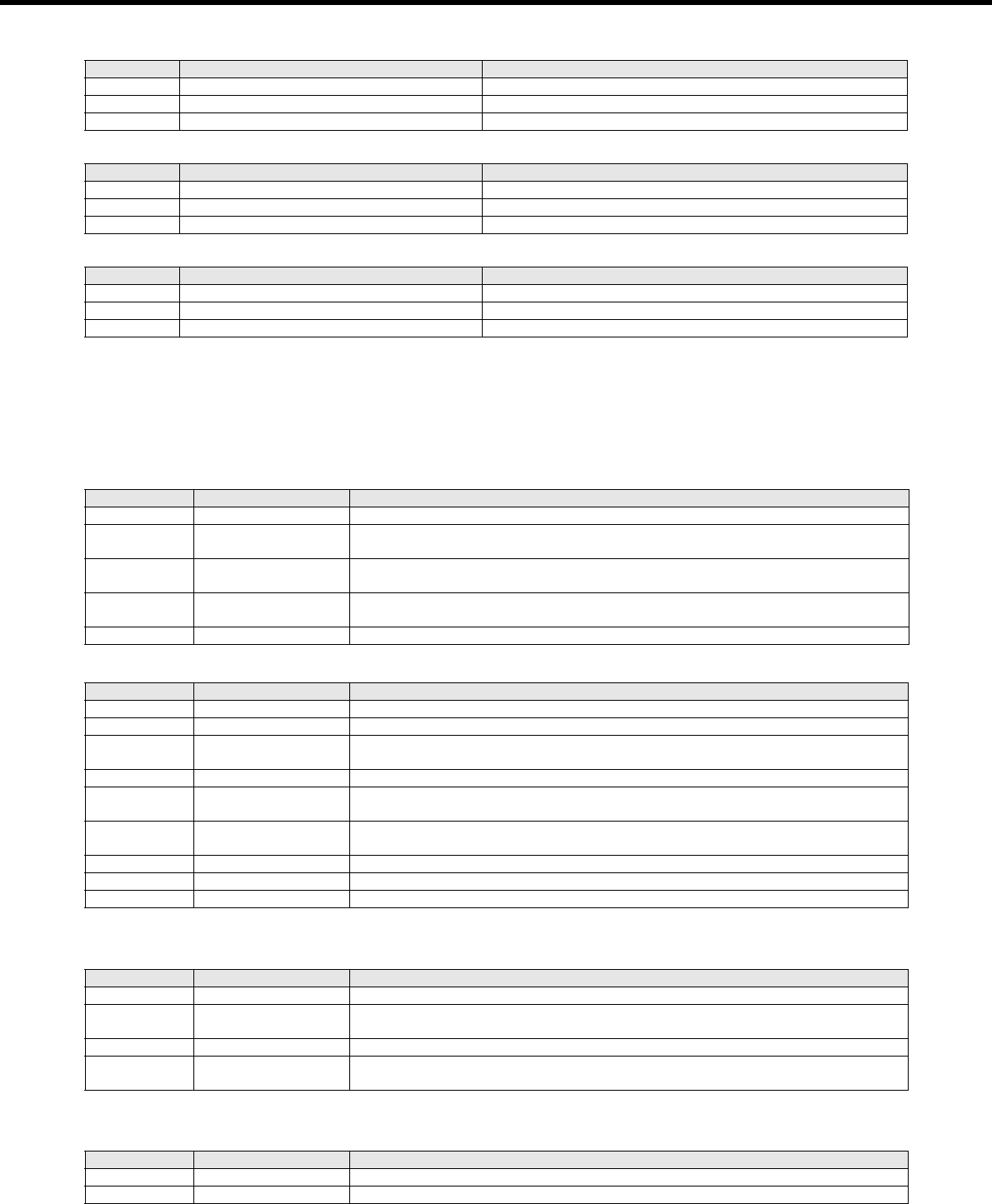
COMP/DUCKER/LEVELER Parameter List
COMPRESSOR
If a signal higher than a specified threshold level is input, the output level is adjusted by a specified ratio.
Type=Comp
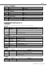
Type=MulitiBand
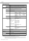
DUCKER
If the selected input source signal level exceeds the specified threshold level, the output level is attenuated by a specified amount (range).
LEVELER
If a signal higher than a specified threshold level is input, the output level is adjusted to the specified level.
Parameter Range Description
Frequency 0.00 – 39.7 Hz Modulation frequency
Depth 0 – 127 Modulation depth
Delay 0.0 – 50.0 ms Delay offset
Parameter Range Description
Depth 0 – 32 Pitch shift depth
Range 0 – 12 Pitch range
Type Sound4 – Sound1, Normal, Rythm1 – Rythm4 Effect type
Parameter Range Description
Cutoff 0 – 127 Filter cutoff
Drive 0 – 127 Distortion drive level
LPF 1.0 kHz – 18.0 kHz, Thru LPF frequency
Parameter Range Description
Threshold -48 to -6 dB This determines the level of input signal required to trigger the compressor.
Ratio 1.0 – 20.0
This determines the amount of compression. A larger value results in a stronger compression
effect.
Attack 1 – 40 ms
This determines how soon the signal will be compressed once the compressor has been trig-
gered.
Release 10 – 680 ms
This determines how soon the compressor returns to its normal gain once the trigger signal
level drops below the threshold.
Out Level -12 to +12 dB This sets the compressor’s output signal level.
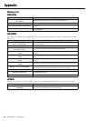
Parameter Range Description
L-M Xover 21.2 Hz – 4.0 kHz Low/mid crossover frequency
M-H Xover 42.5 Hz – 8.0 kHz Mid/high crossover frequency
Release 10 – 3000 ms
This determines how soon the compressor returns to its normal gain once the trigger signal
level drops below the threshold.
Out Level -12 to +12 dB Output level
L(/M/H)-Thresh -54 to -6 dB
This determines the level of input signal required to trigger the low/mid/high band compres-
sor.
L(/M/H)-Ratio 1.0 – 20.0
This determines the amount of low/mid/high band compression. A larger value results in a
stronger compression effect.
L(/M/H)-Attack 1 – 200 ms Low/mid/high band compressor attack
L(/M/H)-Gain -INF, -36 to +18 dB Low/mid/high band compressor gain
L(/M/H)-Bypass ON, OFF Low/mid/high band bypass on/off
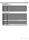
Parameter Range Description
Source
CH24 {CH16}, GROUP1
This determines whether the ducker source signal is channel 24 {16} or GROUP1.
Threshold -60 to 0 dB
This determines the level of trigger signal required to active the ducker. If the source input sig-
nal exceeds this level, the ducker begins to be applied.
Range -70 to 0 dB This determines the amount of attenuation when the ducker is activated.
Release 1 ms – 50 s
This determines how soon the ducker returns to its normal gain once the trigger signal level
drops below the threshold.
Parameter Range Description
Threshold -60 to 0 dB This determines the level of input signal required to trigger the leveler.
Out Gain -20 to +40 dB This sets leveler’s output signal level.


Find Your Products By Category
Please Login
