

0
Owner's of the Yamaha Music Mixer Yamaha Music Mixer gave it a score of 0 out of 5. Here's how the scores stacked up:
MGP32X/MGP24X Owner’s Manual
17
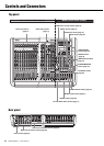
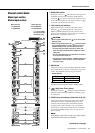
Controls and Connectors
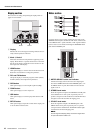
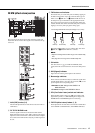
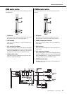
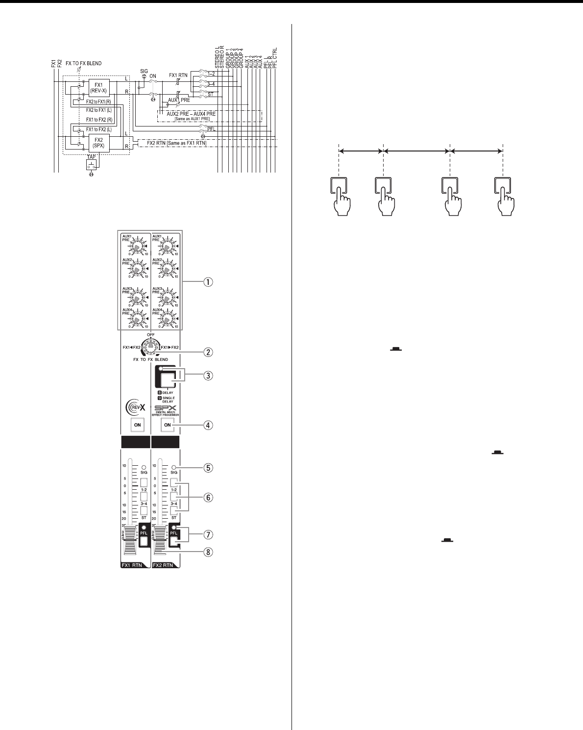
FX RTN (effect return) section
This section sets the effect returns (FX1 and FX2) on/off, and
determines the level of the effect signal and to which bus the sig-
nal is sent.
q AUX (PRE) knobs (1-4)
These knobs adjust the level of the effect sent to the AUX1 to
AUX4 buses.
w FX TO FX BLEND knob
Sends the signal from FX1 to FX2 and from FX2 to FX1.
Rotate this knob from the center “OFF” position to the right to
adjust the send level from FX1 to FX2, and to the left to adjust
the send level from FX2 to FX1. Only the pre-fader signal can
be sent.
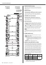
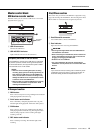
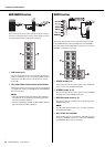
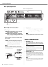
e TAP button and indicator
This feature lets you set the delay time for FX2 by tapping on
the button. This feature only works when the effect type for
FX2 is set to “, DELAY” or “. SINGLE DELAY.” To set
the delay time, tap on the button at the appropriate interval.
The average interval at which you tap the button will be cal-
culated, and that value will be set for the delay time. Continue
tapping as necessary until you get the timing right.
The TAP indicator flashes in sync with the delay time when
, DELAY or . SINGLE DELAY is selected.
NOTE
• Adjust the average interval within range of the variable delay
time.
• See page 44 for the range of the variable delay time.
r ON switch
Turn this switch on
()
to enable the FX RTN (effect
return). When the switch is turned on, the switch’s lamp comes
on.
t SIG (Signal) indicator
Lights when an effect signal is input into the channel.
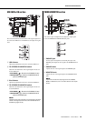
y Bus assign switches
These switches determine the bus(es) to which the signal of the
internal digital effects is sent. Press the switch in
()
to out-
put the signal to the corresponding buses.
• Switches 1-2, 3-4: Assign to the GROUP1 to
GROUP4 buses.
• ST switch: Assigns to the STEREO L/R bus.
u PFL (Pre-Fader Listen) switch and indicator
When the PFL switch is turned on
()
, the indicator will
light and the pre-FX (1, 2) RTN-fader signal is output to the
MONITOR OUT and PHONES jacks for monitoring.
i FX RTN (effect return) faders (1, 2)
These adjust the level of the effect sent from the internal effect
to the GROUP1 to GROUP4 buses, and STEREO L/R buses.
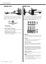
First tap Second tap Third tap Fourth tap
ab c
The average interval will be set (the average of a, b, and c)


Find Your Products By Category
Please Login
