
0
Owner's of the Yamaha Music Mixer Yamaha Music Mixer gave it a score of 0 out of 5. Here's how the scores stacked up:

MGP32X/MGP24X Owner’s Manual
13
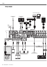
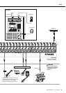
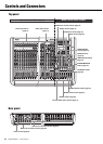
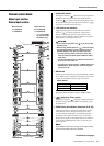
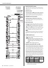
Controls and Connectors
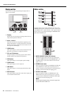
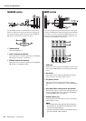
!2 AUX knobs (1-4)
These knobs adjust the channel’s signal levels into AUX
buses 1 to 4. Each knob controls the signal into the corre-
sponding AUX bus. On stereo channels, the LINE L (odd)
and LINE R (even) input signals are mixed before moving
into the AUX bus. These knobs should generally be set close
to the “t” (nominal) position.
NOTE
• To enable use of AUX5 and AUX6, you must turn on ( )
the AUX5/AUX6 switch (!5).
• For AUX1 to AUX4, you use the PRE switch (!3) to select
whether the pre-fader or post-fader signal is sent to the bus.
For AUX5 and AUX6, only the post-fader signal can be sent.
!3 PRE switch
Selects whether the pre-fader or the post-fader signal is fed to
the corresponding pair of AUX 1-4 buses. AUX1 and 2 and
also AUX3 and 4 should be paired. The upper PRE switch
controls the signal to AUX1 and AUX2; the lower switch
controls the signal to AUX3 and AUX4. If the switch is on
( ), the mixer feeds the pre-fader signal to the correspond-
ing buses. If off ( ), the mixer feeds the post-fader signal.
!4 FX (effect) knobs (1, 2)
These knobs adjust the channel’s post-fader signal levels into
FX buses 1 and 2. On stereo channels, the LINE L (odd) and
LINE R (even) input signals are mixed before moving into
the FX bus. These knobs should generally be set close to the
“t” (nominal) position.
NOTE
If the AUX5/AUX6 switch is on, these knobs adjust the output
to the AUX5 and AUX6 buses.
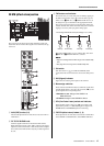
!5 AUX5, AUX6 switch
Selects whether the channel’s post-fader signal is sent to
AUX buses 5 and 6 or FX buses l and 2. If the switch is on
( ), the signal goes to AUX5 and 6 buses; if off ( ), the
signal goes to the FX buses.
!6 PAN knob (Mono channels)
BAL knob (Stereo channels)
These knobs set the stereo pan position and determine the
volume balance between left and right. When the channels
are panned hard left or hard right, sound is heard from only
the hard-panned channel.
The PAN knob determines each mono signal’s pan position-
ing between left and right, while the BAL knob determines
the stereo channel’s volume balance between left and right.
!7 ON switches
Turning this switch on ( ) sends that channel’s signal to
the buses. When the switch is turned on, the switch’s lamp
comes on. If you turn the switch off ( ), all of the signal
sent to the buses such as AUX and GROUP buses is cut off.
NOTE
• The ON switch does not affect the operation of the PFL
switch (@1). You can monitor the channel’s pre-fader signal
through the PHONES jack even when the ON switch is off.
• To reduce noise, turn all unused channels off.
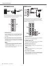
!8 PEAK indicator
Lights red when the channel’s post-equalizer signal level
reaches 3 dB before clipping.
!9 SIG (Signal) indicator
Lights green when a signal is being input to the channel.
@0 Bus assign switches
These switches determine the bus(es) to which each channel’s
signal is sent. Press the switch in ( ) to output the signal to
the corresponding bus.
• Switches 1-2, 3-4: Assign the channel’s signal to the
GROUP 1 to 4 buses.
• ST switch: Assigns the channel’s signal to the STE-
REO L and R buses.
NOTE
To send the signal to each bus, engage the ON switch (!7).
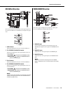
@1 PFL (Pre-Fader Listen) switch and indicator
When the PFL switch is turned on ( ) the indicator comes
on and the channel pre-fader signal is output to the MONI-
TOR OUT and PHONES jacks for monitoring.
@2 Channel fader
Adjusts the output level of the input channel signal. Use these
faders to adjust the balance between the various channels.
NOTE
To reduce noise, set the fader sliders for any unused channels
all the way down.


Find Your Products By Category
Please Login
