
0
Owner's of the Yamaha Music Mixer Yamaha Music Mixer gave it a score of 0 out of 5. Here's how the scores stacked up:
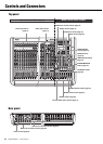
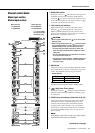
Controls and Connectors
MGP32X/MGP24X Owner’s Manual
16
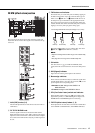
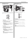
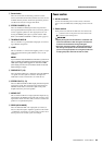
Display section
This section is for setting and operating the display. Refer to
pages 24-25 for details.
q Display
Indicates the various messages and settings related to the cur-
rently selected operation or function.
w Knob 1, Knob 2
Selects/sets the functions and parameters appearing on the
display. Rotate Knob 1 to operate the functions on the lower
left side of the display, and Knob 2 for the functions on the
lower right side of the display.
e HOME button
Calls up the display to view the status of the functions. This
button does not determine or change the parameter.
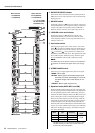
r FX1 and FX2 buttons
Call up the display to switch the programs of FX1 (effect1)
and FX2 (effect2) and to adjust their parameters.
t GEQ button
Calls up the display to set the Graphic equalizer (GEQ).
y COMP button
Calls up the display to set the compressor.
u USB button
Calls up the display to record and play back with the USB
device.
i SETUP button
Calls up the display to adjust the contrast of the display, and
to set the ducker and the leveler.
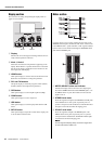
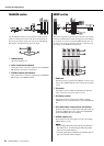
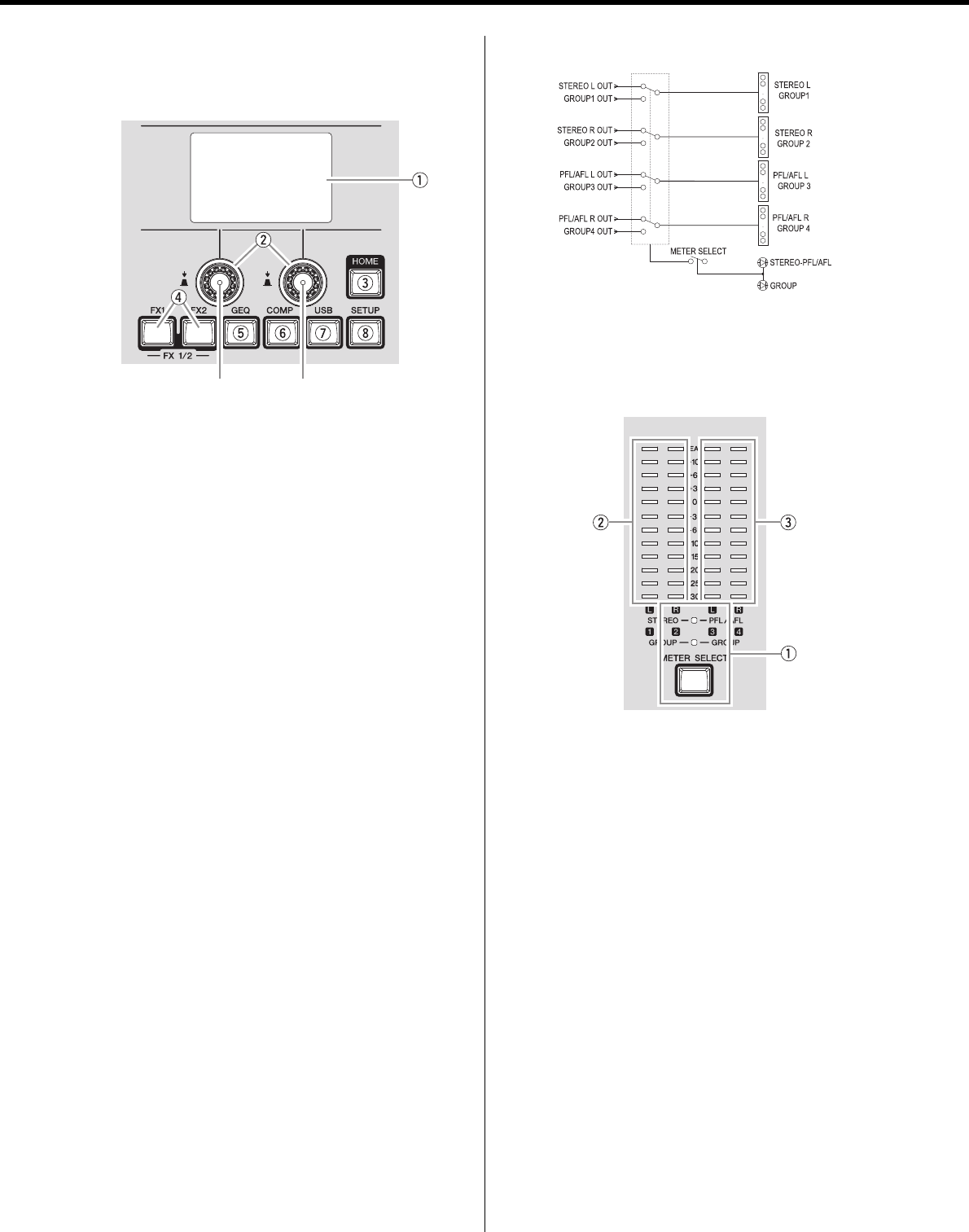
Meter section
Use these meters to view various signal levels: the levels to the
STEREO OUT L/R jacks, the PFL and AFL levels, and the levels
to the GROUP OUT 1-4 jacks. The PFL or AFL signals indicated
by these meters can be monitored through the MONITOR OUT
jacks and the PHONES jack.
q METER SELECT button and indicator
Switches the display of the level meter to the output signal
level of the STEREO OUT L/R and the PHONES jacks, or of
the GROUP OUT 1-4 jacks. The indicators for the selected
signals come on.
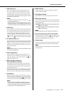
w STEREO level meter
Shows the signal level output to the STEREO OUT L/R jacks
or the GROUP OUT 1 and 2 jacks, respectively. The “0”
position corresponds to the standard level. The PEAK indica-
tor lights red when the level hits the clipping point.
e PFL/AFL level meter
Shows the signal level output to the PHONES jack or the
GROUP OUT 3 and 4 jacks, respectively. The “0” position
corresponds to the standard level. The PEAK indicator lights
red when the level hits the clipping point.
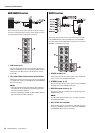
NOTE
The PFL signal has display priority over the AFL signal when
an input channel’s PFL switch is on.
Knob 1 Knob 2


Find Your Products By Category
Please Login
