

0
Owner's of the Yamaha Music Mixer Yamaha Music Mixer gave it a score of 0 out of 5. Here's how the scores stacked up:
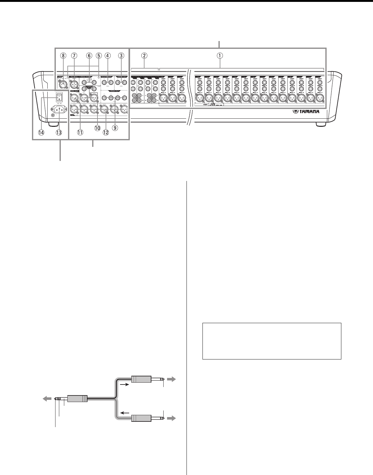
Controls and Connectors
MGP32X/MGP24X Owner’s Manual
22
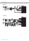
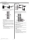
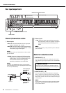
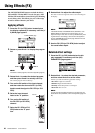
Rear input/output block
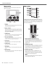
Channel I/O connectors section
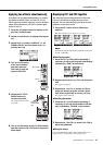
q Mono inputs
• INPUT A: These are balanced XLR-3-31 type input
jacks (1: Ground; 2: Hot; 3: Cold).
• INPUT B: These are TRS phone-jack type balanced
inputs. You can connect either balanced or unbal-
anced phone plugs to these jacks.
NOTE
On any given channel, you may use either an XLR or phone
jack, but not both.
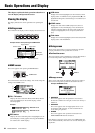
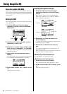
• INSERT: These are unbalanced TRS (tip=send/out;,
ring=return/in; sleeve=ground) phone-type bidi-
rectional jacks. You can use these jacks to con-
nect channels to devices such as graphic
equalizers, compressors, and noise filters.
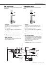
NOTE
Connection to an INSERT jack requires a special insertion
cable as illustrated below. Use a separately-sold Yamaha inser-
tion cable (YIC025/050/070).
w Stereo inputs
• LINE: These are stereo input jacks that connect line-
level instruments, such as a CD player. These are
unbalanced phone-jack and RCA pin-jack line
inputs.
NOTE
On any given channel, you may use either a phone or RCA pin
jack, but not both.
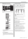
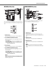
Master I/O connectors section
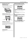
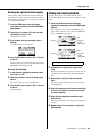
e MATRIX OUT (1, 2)
These are impedance-balanced (*) TRS phone jacks. These
jacks output the signal adjusted by the knobs in the MATRIX
section.
r MONITOR OUT (L, R)
These are impedance-balanced(*) TRS phone output jacks
that you connect to your monitor system. These jacks output
the signal before or after the faders for the various buses. The
PFL and AFL indicators in each section indicate which signal
is being output.
NOTE
The PFL switch has priority when both the PFL switch and AFL
switch are on. To monitor the post-fader signal, make sure to
turn off all PFL switches.
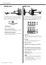
CH25/26-31/32
{CH17/18-23/24}
CH1-24 {CH1-16}
Master I/O connectors section
Power section
Channel I/O connectors section
To the INSERT jack
Sleeve (ground)
Ring: IN
Tip: OUT
To the input jack
of the external
processor
To the output jack
of the external
processor
Tip: OUT
Tip: IN
* Impedance balanced
Since the hot and cold terminals of impedance balanced
output jacks have the same impedance, these output jacks
are less affected by induced noise.


Find Your Products By Category
Please Login
